Cross-Connection Control
The undesirable reversal of flow of water or mixtures of water and other liquids, gases or other substances into the distribution pipes of the potable supply of water from any source or sources.
A uniform force applied over a surface, measured as a force per unit area. Typically water pressure is measured in pounds per square inch or psi.
A form of backflow due to a reduction in system pressure, which causes a sub-atmospheric pressure to exist in the water system.
Any elevation of pressure in the downstream piping system (by pump, elevation of piping, steam pressure, air pressure, etc.) above the supply pressure at the point of consideration, which would cause or tend to cause a reversal of the normal direction of flow.
Either a pollutant (non-health hazard) or contaminant (health hazard); derived from the assessment of the materials, which may come in contact with the distribution system through a cross-connection.
A pollutant is considered to be any substance that would affect the color or odor of the water, but would not pose a health hazard.
A contaminant is considered a health hazard if it causes illness or death if ingested.
Sewage and radioactive materials are considered lethal hazards. This is because of the epidemic possibilities associated with sewage and the tremendous dangers associated with radioactive material.
Any actual or potential connection or structural arrangement between a public or a consumer’s potable water system and any other source or system through which it is possible to introduce into any part of the potable system any used water, industrial fluid, gas, or substance other than the intended potable water with which the system is supplied. Bypass arrangements, jumper connections, removable sections, swivel or change-over devices and other temporary or permanent devices through which or because of which backflow can occur are considered to be cross-connections.
A direct cross-connection is a cross-connection which is subject to both backsiphonage and backpressure.
An indirect cross-connection is a cross-connection which is subject to backsiphonage only.
Backflow Preventers
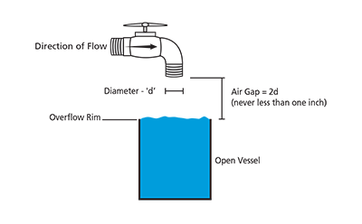 A physical separation between the free flowing discharge end of a potable water supply pipeline and an open or non-pressure receiving vessel.
An “approved air gap” shall be at least twice the diameter of the supply pipe measured vertically above the overflow rim of the receiving vessel; in no case less than 1 inch (2.54 cm).
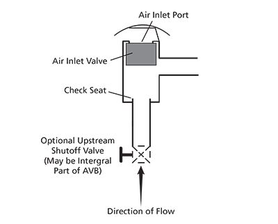 An assembly containing an air inlet valve, a check seat and an air inlet port(s). (Also known as the non-pressure type vacuum breaker.) The flow of water into the body causes the air inlet valve to close the air inlet port(s). When the flow of water stops the air inlet valve falls and forms a check valve against backsiphonage. At the same time it opens the air inlet port(s) allowing air to enter and satisfy the vacuum. A shutoff valve immediately upstream may be an integral part of the assembly, but there shall be no shutoff valves or obstructions downstream. The assembly shall not be subjected to operating pressure for more than twelve (12) hours in any twenty-four (24) hour period.
An atmospheric vacuum breaker is designed to protect against a non-health hazard (i.e., pollutant) or a health hazard (i.e., contaminant) under a backsiphonage condition only.
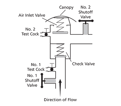 An assembly containing an independently operating internally loaded check valve and an independently operating loaded air inlet valve located on the discharge side of the check valve. The assembly is to be equipped with properly located resilient seated test cocks and tightly closing resilient seated shutoff valves attached at each end of the assembly.
This assembly is designed to protect against a non-health hazard (i.e., pollutant) or a health hazard (i.e., contaminant) under a backsiphonage condition only.
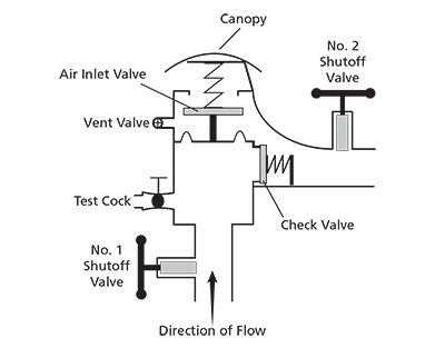 An assembly containing an independently operating internally loaded check valve and independently operating loaded air inlet valve located on the discharge side of the check valve. The assembly is to be equipped with a properly located resilient seated test cock, a properly located bleed/vent port, and tightly closing resilient seated shutoff valves attached at each end of the assembly.
This assembly is designed to protect against a non-health hazard (i.e., pollutant) or a health hazard (i.e., contaminant) under a backsiphonage condition only.
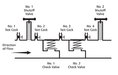 An assembly composed of two independently acting, approved check valves, including tightly closing resilient seated shutoff valves attached at each end of the assembly and fitted with properly located resilient seated test cocks.
This assembly shall only be used to protect against a non-health hazard (i.e., pollutant).
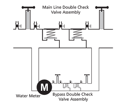 A specially designed assembly composed of a line-size approved double check valve assembly with a bypass containing a specific water meter and an approved double check valve assembly. The meter shall register accurately for rates of flow up to 2 gpm (gallons per minute) and shall show a registration for all rates of flow.
This assembly shall only be used to protect against a non-health hazard (i.e., pollutant). The DCDA is primarily used on fire sprinkler systems.
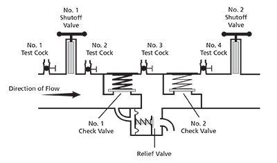 An assembly containing two independently acting approved check valves together with a hydraulically operating, mechanically independent pressure differential relief valve located between the check valves and at the same time below the first check valve. The unit shall include properly located resilient seated test cocks and tightly closing resilient seated shutoff valves at each end of the assembly.
This assembly is designed to protect against a non-health hazard (i.e., pollutant) or a health hazard (i.e., contaminant).
This assembly shall not be used for backflow protection of sewage or reclaimed water. (Note: Check with local administrative authority for acceptable uses.)
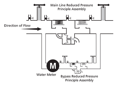 A specially designed assembly composed of a line-size approved reduced pressure principle backflow prevention assembly with a specific bypass containing a specific water meter and an approved reduced pressure principle backflow prevention assembly. The meter shall register accurately for rates of flow up to 2 gpm and shall show a registration for all rates of flow. (See Chapter 10, for additional details.)
This assembly shall be used to protect against a non-health hazard (i.e., pollutant) or a health hazard (i.e., contaminant). The RPDA is primarily used on fire sprinkler systems.